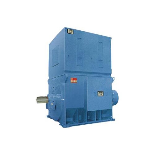
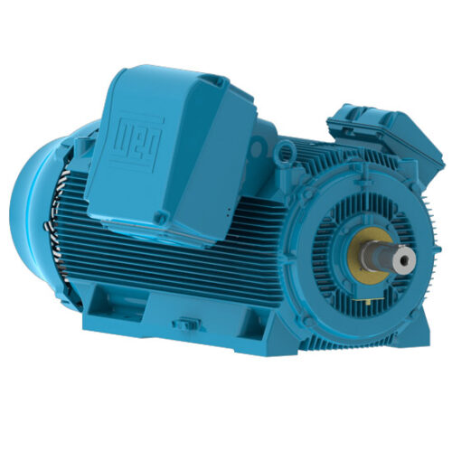
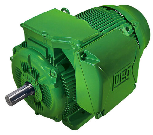
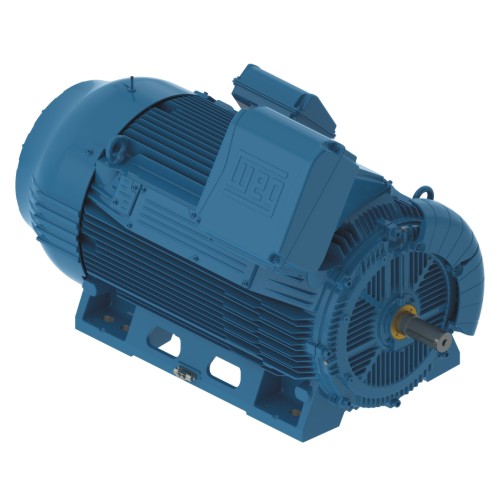
These motors can be designed with configuration to meet cooling method and degree of protection requirements of different kinds of applications.
M Line – MAF – Low and High Voltage – TEAAC – Slip Ring
Description
Description
M Line motors are manufactured in different configurations in reference to cooling methods and degree of protection, allowing the machine to be designed as suitable as possible to meet operation and environment requirements.
Motors in frame sizes IEC 280 to 560 are manufactured in cast iron, while frame sizes IEC 630 and above are fabricated in welded steel plates.
Standard Features
- Sinusoidal power supply of 220 to 13,800 V
- Motors manufactured in 4 to 12 poles
- Cast iron frames 280 to 560 and welded steel plates for frame 630 to 1800
- Cooling methods used:
– Open self-ventilated;
– Self-ventilated by ducts, air inlet and outlet;
– Forced ventilated, air inlet and outlet by ducts;
– Forced ventilation, cooling on top of motor;
– Self-ventilated with air-to-air heat exchanger, heat exchanger on top of motor;
– Self-ventilated with air-to-air heat exchanger, heat exchanger around the stator;
– Forced ventilation in the air internal and external circuit, air-to-air heat exchanger;
– Air-to-water heat exchanger;
– Air-to-water heat exchanger, forced ventilation in the air internal circuit - Mounting: B3
- Degree of Protection: IP23 to IP55
- Service duty: (S1)
- Class of insulation: F
- Service Factor: 1.0
- Temperature rise: 80 °C
- Ambient temperature: 40 °C
- Altitude: 1000 m
- Temperature detector: Pt100, 1 per bearing with 3 wires
- Temperature detector: Pt100, 2 per phase with 3 wires
- Two accessory terminal boxes, one for signal accessories and the other for those accessories requiring power supply (space heaters)
- Single phase space heater
- Labyrinth tachonite in grease lubricated bearings
- Grease lubricated bearings:
– For 4 pole motors in the following frame sizes:
– Up to frame 560 (inclusive) for 60 and 50 Hz;
– Grease lubricated bearings for 6 pole motors and above - Sleeve bearings:
– For 4 pole motors in frame 630 - Electrically insulated non-drive end bearing for frames 450 and above, when connected directly to the power supply
- Painting: Acrylic polyurethane Polyamide epoxy (Final coat: Blue RAL 5007)
- Stainless steel nameplate
- Grounding lug on the frame and terminal box
- Stainless steel slip rings
- Rotor terminal box separated from stator terminal box
- Compartment of slip rings and brushes separated from stator and rotor, behind the non-drive end bearing
- Grounding brush on the drive end shaft for frames 450 and up
- Automatic / manual brush lifting system
- 03 connection terminals in the power terminal box for high voltage (with terminal block)
- 06 loose power connection leads for low voltage (without terminal block)
Optional Features
- VFD application
- Service Factor: 1.15
- Class of insulation: H
- Temperature rise: 105°K for class F
- Temperature rise: 125°K for class H
- Ambient temperature above 40 °C (on request)
- Altitude above 1000 m (on request)
- Mountings: B5, B35, V1, V3, V5, V6, V18, V19, V36
- Degree of Protection IPW55 and above
- Classified area application: Ex-p
- Special balance
- Base: rail, sliding base, extended feet, rebuilt feet, anchorage plate
- Steel welded terminal box in different sizes based on internal available space
- Power factor correction capacitors
- Non-reversion ratchet
- Centrifugal switch
- Temperature detector: Thermistor (PTC or NTC)
- Temperature detector: Thermostat (Bimetallic)
- Two energized power terminal boxes
- Space heaters
- One or more accessory terminal boxes
- Shaft: Special dimensions, double shaft end, tapered, hollow, special steel
- Encoder
- Sleeve bearing
- Oil lubricated bearing
- Special bearing (overdesigned) for axial or radial thrust
- Special painting
- Terminal block for low voltage
- Cable gland in the terminal box entrance
- Protection against voltage surge: Lighting arrestors and Capacitors
- Aluminum, copper or brass rotor
- Vibration detector
- Noise suppressor in the air inlet and outlet
- Tachogenerator
- CT for differential and integral protection
- Bearing thermometer with gauge with/without contacts
- Signal transducer
- Independent hydraulic oil circulation system for sleeve bearing
- Electrically insulated non-drive end bearing for all frame sizes with driven by frequency drive
- Both bearings are electrically insulated
- Grounding brush on drive end bearing for all frames when driven by frequency converter (except for classified area)


